HomeVent ER / ERT in apartment buildings - What Planners need to know
This blog is aimed at planners and shows what needs to be considered when designing HomeVent ER / ERT comfort ventilation systems in new or existing buildings.
- Blog
- Expert - Engineer
Planning modern apartment buildings places high demands on energy efficiency, comfort and indoor air quality. With increasingly impermeable building envelopes in particular, controlled residential ventilation is essential to ensure a healthy indoor climate, prevent damp and mould and minimise ventilation heat losses – HomeVent ER / ERT meets all relevant standards and integrates into large residential complexes in a powerful, quiet and space-saving way.
1. Basics of planning comfort ventilation
When planning comfort ventilation in residential buildings, it is first necessary to clearly define the ventilation concept. The type, number, area and utilisation of the rooms included in the ventilation system as well as the underlying floor plans and clear room heights are central to this.
Possible installation routes for distribution ducts and outlets (e.g. in ceilings, shafts, floor structures or exterior walls) should also be considered at an early stage so that the ventilation system can be planned in harmony with the supporting structure, building services and interior fittings.
Other requirements – such as acoustic insulation, fire protection, building physics and design in accordance with standards – are discussed later in the article.
Note: One comfort ventilation unit must always be assigned to one residential unit. The application limits defined by Hoval for flow rate, pressure drop and temperature range must be observed.
2. HomeVent ER or ERT: Overview of the system
2.1 Enthalpy heat recovery of the HomeVent ER / ERT
HomeVent uses enthalpy heat recovery (HR) with a rotary heat exchanger that transfers heat with an efficiency of up to 85% and humidity with up to 90% from the extract air to the supply air. This typically reduces the heating requirement by around 20 – 45%, while the indoor climate remains stable at a comfortable humidity and temperature level.
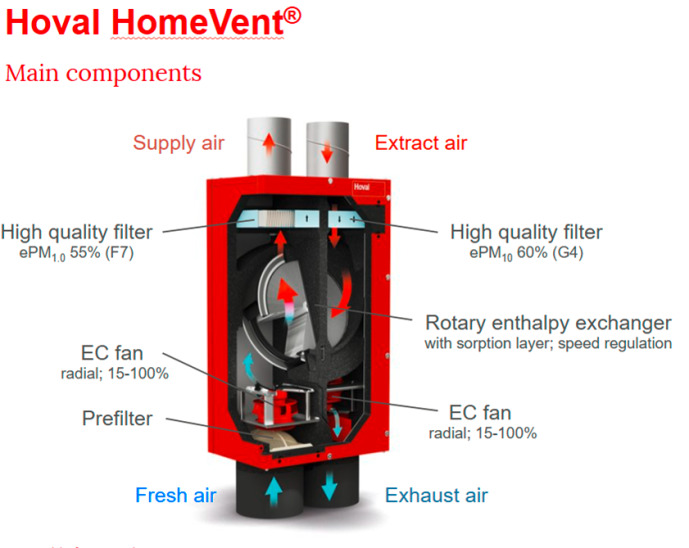
Figure 1: Structure of the Hoval HomeVent
2.2 Condensate-free – unique selling point of HomeVent ER / ERT
HomeVent ER / ERT do not require a condensate drain, as the moisture from the extract air is transferred to the supply air by means of an enthalpy exchanger and therefore no condensate is produced in the unit. While the HomeVent ERT is designed for upright installation on the floor with all 4 connections facing upwards, the HomeVent ER can be installed in any conceivable installation orientation. This simplifies planning and installation enormously. The EPP insulation also enables external installation (façades/balconies) and eliminates the risk of icing – even at low outdoor temperatures (down to −20 degrees Celsius).
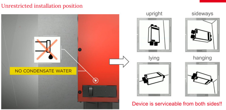
Figure 2: Possible installation positions HomeVent ER
2.3 Target values for air exchange planning (guide values!)
The following guide values have proven to be useful for the design of HomeVent devices: air exchange rate approx. 0.3 – 0.6 h-¹ and a relative humidity of 40 – 60%. For a 100 m² flat with 3 – 4 people, an air exchange rate of 0.4 – 0.5 h-¹ or a supply air volume of around 40 – 50 m³/h per person or room zone can be assumed and will provide a very high level of comfort.
3. Framework conditions for planning and operation
3.1 Acoustic protection: should be considered as early as the design phase
Sound sources in central ventilation systems can lead to noise immissions in living areas if acoustic insulation measures are neglected. Sound-insulated housings, suitable silencers in supply and extract air ducts and vibration-decoupled installation of the devices are therefore an integral part of the planning:
- Clear separation of technical areas from living areas, and targeted routing of air ducts to minimise operating noise.
- To avoid nuisance – for example on terraces or for neighbours – it is also recommended for silencers in exhaust air ducts and, if necessary, fresh air ducts.
- Distribution ducts should normally remain within a length range of around 6 – 15 m.
3.2 Terms and spatial organisation
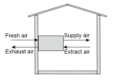
Clear terminology is helpful for planning: fresh air becomes supply air in the unit, while extract air is discharged to the outdoor as exhaust air after heat recovery:
Depending on the use to which they are put, rooms are divided into supply air, transfer and extract air zones:
Zone | Room use (examples) |
Supply air zone | Bedroom, living room, nursery, dining room |
Transfer zone | Corridor, hallway, stairway |
Extract air zone | Bathroom, toilet, shower, kitchen, storage room, hall |
Rooms equipped with comfort ventilation should be located within the thermal building shell. Supply and extract air openings in the same room only make sense in justified special cases and are generally avoided.
3.3 Defining flow rates
The required flow rates must be determined on a project-specific basis using the current status of standards. In addition to the number of people, the room size, moisture loads, acoustic insulation requirements and temperature conditions must also be taken into account.
For the design, a nominal ventilation is defined that results from the largest of the following four flow rates, in which case the sum of the extract air flow rates should correspond to a maximum of 1.2 times the area-related nominal ventilation from Table 2. For operating conditions with intensive ventilation, the ventilation unit should be able to provide around 1.3 times the nominal ventilation with typical external pressure drops (e.g. 170 Pa).
Bases of calculation and tables at a glance:
- A flow rate of about 30 m³/h must be provided per person.
- The area-related minimum flow rates of the utilisation unit must be complied with in accordance with Table 2.
- For extract air rooms, the minimum flow rates according to Table 3 must be taken into account.
- The flow rates specified in Table 4 are recommended for supply air rooms.

Table 2: Nominal ventilation VR (room volume), NL (nominal ventilation) according to utilisation unit area ANE (fresh air flow rate per utilisation unit)
Reference value for the basic dimensioning per utilisation unit:
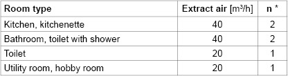
Table 3: Guide values for extract air rooms (* n = usual number of connected flexible pipes DN 75)
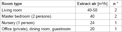
Table 4: Guide values for supply air rooms (* n = usual number of connected flexible pipes DN 75)
Table 5: Relevant area Aüld of transfer air openings with fan-assisted ventilation
Compliance with the values limits the pressure drop across door transfer openings and ensures a functioning transfer between the room zones.
In addition, the free cross-sections of transfer air openings – typically doors with or without seals – must be taken into account in fan-assisted systems.
Additional info: Download project example with ground floor and upper floor, 190 m³/h
3.4 Device installation and supply/extract air routing
Comfort ventilation units from the ER series can be installed in various locations, for example on the wall, under the ceiling or on the floor, with variable arrangement of the fresh air connections at the top or bottom. The inspection cover on both sides enables a mirror-image mounting. Devices and attachments must remain easily accessible for maintenance and servicing!
Only directly or indirectly heated rooms are included in the ventilation. Where possible, all supply and extract ducts must be routed within the insulated building envelope. The position of the supply air, transfer air and extract air openings must be selected such that effective cross-ventilation occurs. The supply air outlets should not be positioned in the immediate occupied area, especially not above the head ends of beds, desks or sofas.
The external pressure drops for fresh air/supply air and extract air/exhaust air including distributor and silencer should not exceed approx. 100 Pa for nominal ventilation. On the room side, a maximum pressure drop of around 40 Pa is recommended. Flow rates in excess of 27 m³/h must be distributed between two ducts. The distributors must be accessible for inserting throttle orifices and for cleaning!
Ducts between the ventilation unit and the supply air distributor or extract air manifold are generally routed with the diameter of the unit coupling and are insulated in cool rooms.
3.5 Fresh and exhaust air
The intake opening for the fresh air must be positioned so that no pollutants or odours – for example from garages, rubbish bins or busy roads – are drawn in. It should be at least approx. 2 m above the ground surface and take into account the main wind direction. Suitable activated carbon filters can also be used for applications with increased odour pollution in the fresh air.
The exhaust air outlet must be arranged in such a way as to avoid a short circuit with the fresh air intake: a minimum horizontal distance of at least 2 m has proven to be effective. The fresh and exhaust air ducts must be insulated to ensure full vapour diffusion-tightness and prevent condensation forming on the duct surface. In practice, Hoval uses 25 mm EPDM insulation, for example.
When routing in shafts, the temperature and humidity conditions prevailing there must be taken into account, and the insulation must be routed through the outer wall at least to just below the outside surface.
3.6 Fire protection – an integral part of planning
Ventilation systems must maintain fire compartments, which is why fire protection measures are an integral part of planning from the outset. Materials and insulating materials must be selected in accordance with the required fire resistance classes, and ventilation ducts and partition walls must be routed in such a way that smoke and heat dissipation and safe compartmentalisation are guaranteed in the event of fire. The respective fire protection requirements must be agreed with the responsible expert.
4. TopTronic E
The TopTronic E controller seamlessly connects the HomeVent ER or ERT to the building automation system. It supports common interfaces such as KNX, OpenTherm and 0-10 V for coordination with heating circuits and domestic water heating. Flow rate, temperature, humidity and filter status can be analysed centrally.
4.1 HomeVent ER / ERT with 3½-level architecture for maximum flexibility
- Level 1: Device (sensors, fans, heat recovery)
- Level 2: Basic regulation (autonomous)
- Level 3: TopTronic E (room control module)
- Level 3½: Building automation + cloud monitoring
6. Webinar On-Demand:
Direct link to the webinar with more information:
Using HomeVent in apartment buildings – what planners need to know
Agenda:
- Introduction to domestic ventilation: basics and key requirements
- Challenges as part of planning ventilation systems in apartment buildings
- Hoval HomeVent: efficiency, operating advantages and perceptible added value for users, owners and planners
- Practical examples for the successful use of the Hoval solution in apartment buildings
Your Hoval contact will be happy to provide you with further information and individual consulting!